Example of Configuring LLB
This section describes an inbound LLB configuration example.
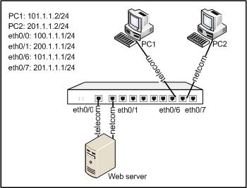
Ethernet0/6 and ethernet0/7 are connected to telecom and netcom links respectively. With inbound LLB enabled, the device will return the IP address defined in the ISP static address named telecom after receiving a DNS request from netcom users, and will return the IP address defined in the ISP static address named telecom after receiving a DNS request from telecom users. The network topology is shown as below:
Take the following steps:
Step 1: Configure ISP information:
- On the Navigation pane, click Configure > Network > Routing to visit the Routing page.
- On the ISP Profile tab, click New.
- In the ISP Configuration dialog, configure options as below:
- ISP profile: telecom
- Subnet prefix: 101.1.1.0
- Subnet mask: 255.255.255.0
- Click Add to add the subnet to the ISP profile. The subnet will be displayed in the ISP subnet list below.
- Click OK to save your settings.
- Repeat Step 2 to Step 5 to create another ISP profile:
- ISP profile: netcom
- Subnet prefix: 201.1.1.0
- Subnet mask: 255.255.255.0
Step 2: Enable SmartDNS and configure a SmartDNS rule table:
- On the Navigation pane, click Configure > Network > LLB to visit the LLB page.
- Click the Inbound tab.
- In the Inbound LLB page, click Enable SmartDNS to enable SmartDNS (skip this step if SmartDNS is already enabled).
- Click New on the upper-left.
- In the Domain Configuration dialog, configure options as below:
- Domain: www.test.com
- ISP static address: telecom
- IP:100.1.1.2
- Weight: 10
- Inbound interface: ethernet0/0
- Track object: N/A
- Click Add to add the configured SmartDNS rule to the rule table.
- Repeat Step 4 to Step 5 to create another SmartDNS rule:
- Domain: www.test.com
- ISP static address: netcom
- IP: 200.1.1.2
- Weight: 10
- Inbound interface: ethernet0/1
- Track object: N/A
- Click OK to save your settings.
When PC1 requests www.test.com, the device will return the IP address for telecom link 100.1.1.2; when PC2 requests www.test.com, the device will return the IP address for netcom link 200.1.1.2.