PnPVPN Configuration Example
This section describes an example of PnPVPN configuration.
A company has its headquarters in Beijing and two branch offices in Shanghai and Guangzhou, all three of which have Internet access. Its business demands that a VPN network should be established. The goals of the network are:
- Employees in Guangzhou Branch and Shanghai Branch can access the headquarters database via VPN;
- All the employees (including the Beijing headquarters and two branches) can share resources via VPN.
PnPVPN is a practical and easy-to-use method to meet the requirements above. Take the following steps:
- The headquarters uses a security gateway as the PnPVPN Server and chooses the local authentication.
- Each of the two branches has a security gateway, working as the PnPVPN Client and accessing the headquarters VPN network.
- To share resource among all employees in the three places, you should configure policies and routes.
The topology is shown below:
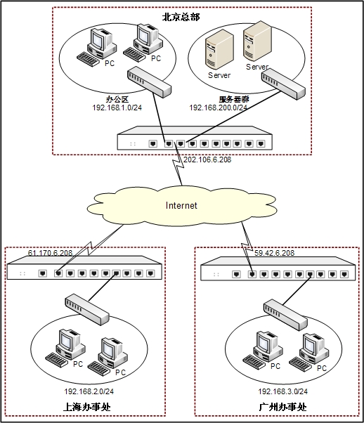
According to the topology, the network environment can be described as follows:
- The headquarters LAN network segment is 192.168.1.0/24 and it uses ethernet0/0 of zone trust to access the network.
- The headquarters server group network segment is 192.168.200.0/24 and it uses ethernet0/2 of zone trust to access the network.
- The headquarter security device use ethernet 0/1 (IP: 202.106.6.208) of zone untrust to access the network.
- Shanghai Branch uses an interface of IP 61.170.6.208 to access the Internet, and Guangzhou Branch uses an interface of IP 59.42.6.208 to access the Internet.
- PnPVPN Server will allocate the network segment 192.168.2.0/2 to Shanghai Branch and 192.168.3.0/24 to Guangzhou Branch.
Take the steps below:
Step 1: Configure the local AAA server
- Select Objects > AAA Server from the menu bar.
- In the AAA Server dialog, click New and select Local Server from the drop-down list.
- In the Local Server Configuration dialog, type test into the Server name box.
- Click OK to save the settings. Click
 to close the dialog.
Step 2: Configure the network in Shanghai Branch
- Select Objects > AAA Server from the menu bar.
- In the Local User dialog, select test from the Local server list. Click New, and then select User from the drop-down list.
On the Basic tab, configure the options as below:
- Name: shanghai
- Password: shanghaiuser
- Confirm password: shanghaiuser
- IKE ID: FQDN
- IKE ID: shanghai
On the PnPVPN tab, configure the options as below:
- DHCP start IP: 192.168.2.1
- DHCP end IP: 192.168.2.100
- DHCP netmask: 255.255.255.0
- DHCP gateway: 192.168.2.101
- Click OK to save the settings.
- In the Local User dialog, select shanghai from the user list and click Edit. In the Edit User dialog, click the PnPVPN tab.
- Click Choose next to the Tunnel route box. In the Configuring Tunnel Route dialog, add the following routes: 192.168.200.0/24, 192.168.1.0/24 and 192.168.3.0/24.
- Click OK to save the settings. In the Edit User dialog, click OK.
Step 3: Configure the network in Guangzhou Branch
- In the Local User dialog, select test from the Local server list. Click New, and then select User from the drop-down list.
On the Basic tab, configure the options as below:
- Name: guangzhou
- Password: guangzhouuser
- Confirm password: guangzhouuser
- IKE ID: FQDN
- IKE ID: guangzhou
On the PnPVPN tab, configure the options as below:
- DHCP start IP: 192.168.3.1
- DHCP end IP: 192.168.3.100
- DHCP netmask: 255.255.255.0
- DHCP gateway: 192.168.3.101
- Click OK to save the settings.
- In the Local User dialog, select guangzhou from the user list and click Edit. In the Edit User dialog, click the PnPVPN tab.
- Click Choose next to the Tunnel route box. In the Configuring Tunnel Route dialog, add the following routes: 192.168.200.0/24, 192.168.1.0/24 and 192.168.2.0/24.
- Click OK to save the settings. In the Edit User dialog, click OK. Click to close the dialog.
Step 4: Configure PnPVPN Server
- On the Navigation pane, click Configure > Network > IPSec VPN to visit the IPSec VPN page. Click the Phase1 Proposal tab.
- Click New. In the Phase1 Proposal Configuration dialog, configure the options as below:
- Proposal name: test1
- Authentication: pre-share
- Hash: SHA-1
- Encryption: 3DES
- DH group: Group2
- Lifetime: 86400
- Click OK to save the settings.
- Click the Phase2 Proposal tab.
- Click New. In the Phase2 Proposal Configuration dialog, configure the options as below:
- Proposal name: test2
- Protocol: ESP
- Hash 1: SHA-1
- Encryption 1: 3DES
- PFS group: No PFS
- Lifetime: 28800
- Click OK to save the settings.
- Click the VPN Peer List tab.
- Click New. In the Peer Configuration dialog, configure the options as below:
- Peer name: test1
- Interface: ethernet0/1
- Mode: Aggressive
- Type: User group
- AAA server: test
- Proposal 1: test1
- Pre-shared key: 123456
- Click Generate next to User key. In the Generate User Key dialog, use the following settings:
- Generate the user key of Shanghai client: type shanghai into the IKE ID box and 123456 into the Pre-shared key box, and click Generate. The generated user key (kyZAKmLWCc5Nz75fseDiM2r+4Vg=) will be displayed in the Generate result box. PnPVPN Client uses this key as the password to authenticate the login users. Click .
- Generate the user key of Guangzhou client: type guangzhou into the IKE ID box and 123456 into the Pre-shared key box, and click Generate. The generated user key (SdqhY4+dPThTtpipW2hs2OMB5Ps=) will be displayed in the Generate result box. PnPVPN Client uses this key as the password to authenticate the login users. Click .
- Click OK to save the settings.
- Click the IPSec VPN tab.
- Click New on the upper-left of the IKE VPN list. In the IKE VPN Configuration dialog, click Import next to Peer name of Step 1: Peer and select test1 from the drop-down list. Or you can create a new peer (ISAMP gateway).
- Click Step 2: Tunnel to configure VPN tunnel. On the Basic tab, configure the options as below:
- Name: test
- Mode: tunnel
- P2 proposal: test2
- Proxy ID: Auto
On the Advanced tab, configure the options as below:
- DNS1: 192.168.200.1
- DNS2: 192.168.200.11
- WINS1: 192.168.200.2
- WINS2: 192.168.200.12
- Click OK to save the settings.
Step 5: Configure policies
- On the Navigation pane, click Configure > Network > Network to visit the Network page.
- Click New on the upper-left of the zone list. In the Zone Configuration dialog, configure the options as below:
- Name: VPN
- Type: Layer 3 zone
- Click OK to save the settings.
- Click New on the upper-left of the interface list, and select Tunnel Interface from the drop-down list. In the Interface Configuration dialog, configure the options as below:
- Name: tunnel1
- Binding zone: Layer 3 zone
- Zone: VPN
- Tunnel type: IPSec
- VPN Name: test
- Click OK to save the settings and return to the Network page.
- On the Navigation pane, click Configure > Security > Policy to visit the Policy page.
- Click New. In the Policy Configuration dialog, configure the options as below:
- Src zone: VPN
- Src address: Any
- Dst zone: trust
- Dst address: Any
- Service: Any
- Action: Permit
- Click OK to save the settings.
- In the Policy page, click New. In the Policy Configuration dialog, configure the options as below:
- Src zone : trust
- Src address: Any
- Dst zone: VPN
- Dst address: Any
- Service: Any
- Action: Permit
- Click OK to save the settings.
- In the Policy page, click New. In the Policy Configuration dialog, configure the options as below:
- Src zone: VPN
- Src address: Any
- Dst zone: VPN
- Dst address: Any
- Service: Any
- Action: Permit
- Click OK to save the settings.
Step 6: Configure routes
- On the Navigation pane, click Configure > Network > Routing to visit the Routing page.
- On the Destination Route tab, click New. In the Destination Route Configuration dialog, configure the options as below:
- Destination: 192.168.2.0
- Subnet mask: 255.255.255.0
- Next hop: Interface
- Interface: tunnel1
- Gateway: 61.170.6.208
- Click OK to save the settings.
- On the Destination Route tab, click New. In the Destination Route Configuration dialog, configure the options as below:
- Destination: 192.168.3.0
- Subnet mask: 255.255.255.0
- Next hop: Interface
- Interface: tunnel1
- Gateway: 59.42.6.208
- Click OK to save the settings.
Step 7: Configure clients
Shanghai Branch
- On the Navigation pane, click Configure > Network > IPSec VPN to visit the IPSec VPN page to visit the IPSec VPN page.
- On the Task tab in the right auxilary pane, click PnPVPN Client. In the PnPVPN Configuration dialog, configure the options as below:
- Server address: 202.106.6.208
- ID: shanghai
- Password: kyZAKmLWCc5Nz75fseDiM2r+4Vg=
- Confirm password: kyZAKmLWCc5Nz75fseDiM2r+4Vg=
- Auto save: Select the Enable check box
- Outgoing IF: ethernet0/0
- Incoming IF: ethernet0/3
- Click OK to save your settings.
Guangzhou Branch
- On the Navigation pane, click Configure > Network > IPSec VPN to visit the IPSec VPN page to visit the IPSec VPN page.
- On the Task tab in the right auxilary pane, click PnPVPN Client. In the PnPVPN Configuration dialog, configure the options as below:
- Server address: 202.106.6.208
- Local ID: guangzhou
- Password: SdqhY4+dPThTtpipW2hs2OMB5Ps=
- Confirm password: SdqhY4+dPThTtpipW2hs2OMB5Ps=
- Auto save: Select the Enable check box
- Outgoing IF: ethernet0/0
- Incoming IF: ethernet0/3
- Click OK to save your settings.