Example 2: L2 Traffic Transmission among Multiple VSYSs via Shared VSwitch
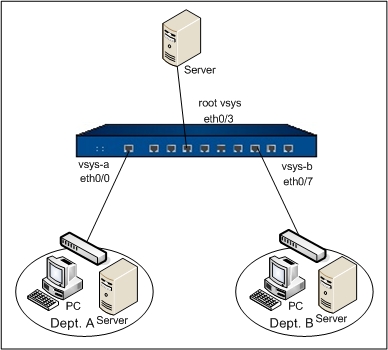
An enterprise deploys a Hillstone device in its network. VSYS-a is configured for Dept. A, and VSYS-b is configured for Dept. B. The interface ethernet0/0 is used by VSYS-a only and etherent0/7 is used by VSYS-b only. The interface etherenet0/3 is shared by Dept. A and Dept. B, and the two departments visit an Intranet server through ethernet0/3. See the topology below:

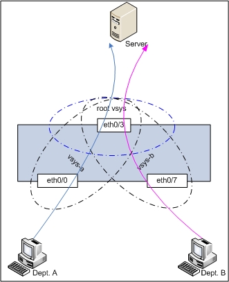
To meet the above requirement, the shared VSwitch and corresponding policy rules are needed. Below is the logical illustration.

Take the following steps:
Step 1: Configure ethernet0/3 of root VSYS.
- On the Navigation pane, click Configure > Network > Network to visit the Network page.
- Select ethernet0/3 from the interface list, and click Edit. In the Interface Configuration dialog, configure as below:
- Binding zone: Layer 2 zone
- Zone: l2-trust
- Click OK to save the changes and return to the Network page.
Step 2: Create VSYS-a and VSYS-b, configure VSwitch1 to be a shared VSwitch, and l2-trust to be a shared zone.
- On the Navigation pane, click Configure > Network > VSYS to visit the VSYS page.
- Click New. In the Configuration dialog, configure as follows:
- Name: vsys-a
- Interface Binding: Select ethernet0/0, and click Physically Import.
- Quota: Select default-vsys-profile
- Click OK.
- Click New. In the Configuration dialog, configure as follows:
- Name: vsys-b
- Interface Binding: Select ethernet0/7, and click Physically Import.
- Quota: Select default-vsys-profile
- Click OK.
- Click Share Resource, and in the Share Resource dialog, configure as follows:
- VSwitch tab : select VSwitch1 and click Share.
- Zone tab: select l2-trust and click Share.
- Click Close to close the Share Resouce dialog.
Step 3: Configure VSYS-a.
- On the Navigation pane, click Configure > Network > VSYS to visit the VSYS page.
- Click VSYS-a in the VSYS list to enter the VSYS-a configuration page.
- On the Navigation pane of VSYS-a, click Configure > Network > Network to visit the Network page.
- Under the Task tab in the right pane, click VSwitch.
- In the VSwitch dialog, Click New.
- Type 2 into the VSwitch name box in the VSwitch Configuration dialog.
- Click OK to close the dialog.
- Click New on upper-left of the Zone list, and configure as follows:
- Name: a-l2
- Type: Layer 2 zone
- VSwitch: vswitch1
- Click OK.
- Select ethernet0/0 from the interface list, and click Edit. In the Interface Configuration dialog, configure as below:
- Binding zone: Layer 2 zone
- Zone: a-l2
- Click OK to save the changes and return to the Network page.
- On the Navigation pane of VSYS-a, click Configure > Security > Policy to visit the Policy page.
- Click New. In the Policy Configuration dialog, configure as follows:
- Src zone: a-l2
- Dst zone: l2-trust
- Src address: Any
- Dst address: Any
- Service: Any
- Action: Permit
- Click OK to save the changes.
Step 4: Configure VSYS-b.
- On the Navigation pane, click Configure > Network > VSYS to visit the VSYS page.
- Click VSYS-b in the VSYS list to enter the VSYS-b configuration page.
- On the Navigation pane of VSYS-b, click Configure > Network > Network to visit the Network page.
- Under the Task tab in the right pane, click VSwitch.
- In the VSwitch dialog, Click New.
- Type 3 into the VSwitch name box in the VSwitch Configuration dialog.
- Click OK to close the dialog.
- Click New on upper-left of the Zone list, and configure as follows:
- Name: b-l2
- Type: Layer 2 zone
- VSwitch: vswitch1
- Click OK.
- Select ethernet0/7 from the interface list, and click Edit. In the Interface Configuration dialog, configure as below:
- Binding zone: Layer 2 zone
- Zone: b-l2
- Click OK to save the changes and return to the Network page.
- On the Navigation pane of VSYS-b, click Configure > Security > Policy to visit the Policy page.
- Click New. In the Policy Configuration dialog, configure as follows:
- Src zone: b-l2
- Dst zone: l2-trust
- Src address: Any
- Dst address: Any
- Service: Any
- Action: Permit
- Click OK to save the changes.


